 All materials on this site © PAR Electronics, Inc.
PAR Electronics, Inc.
P.O Box 645
Glenville, NC 28736
Voice: 828-743-1338
Fax: 866-304-8479
Email us if you have questions or comments about this site.
Site by
Pinnacle Web Design
Vintage Radio Restoration - WRL DuoBander
Please click each image below to enjoy a larger view.
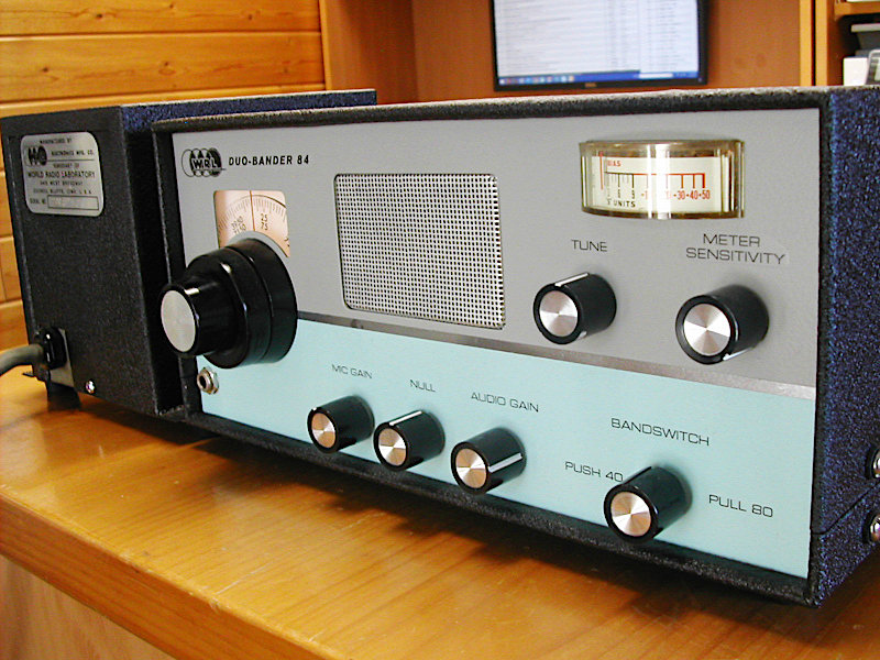
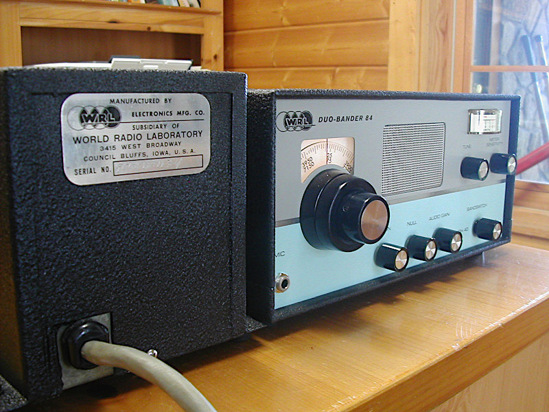
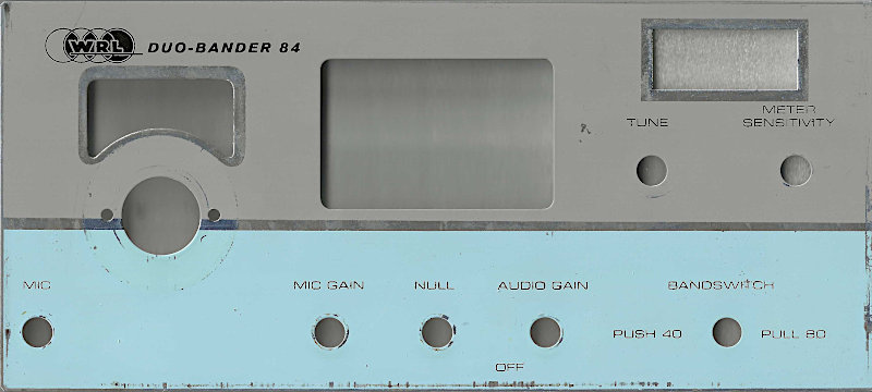
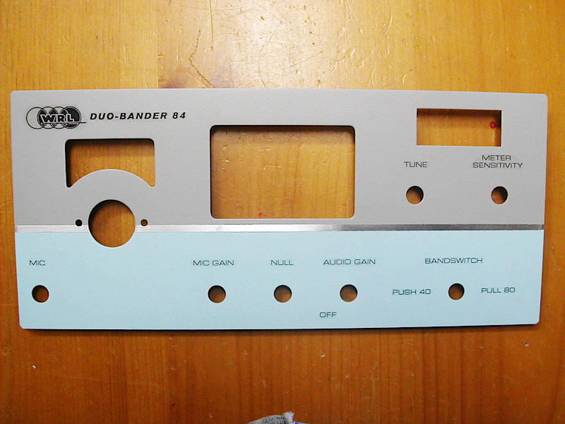
The Duo Bander had fascinated me for some time. A 40/80 meter SSB rig for $159 was a real buy back in its day (1966). However, finding a clean one was next to impossible. I saw some that had been stripped, repainted and hand lettered, and others where the front panel paint was badly flaking. While I awaited just the right Duo Bander, I was restoring another WRL rig- the 6M TC-6A. A WRL power supply showed up on eBay and thinking it was for the TC-6A. I bought it. When it arrived it was obvious this supply was not for a receiver- but either a transmitter or transceiver. WRL often does not put the model number on the power supplies. But a schematic look-up verified what I had was a PS-300 and it was suitable for a Duo Bander. So I now had the cart and got serious about the horse. One offer never panned out but then a Duo Bander showed up on eBay. When it arrived it was very similar to photos I had seen of other Duo Banders. There was missing paint and paint flaking on the front panel along with the years of dings and scratches. Mine even had fingerprints in the paint! So I scanned the panel into the computer and went off to Napa Auto to have them match the 2 colors and put the paint in spray cans. Once you begin sanding the original finish off the front panel- you know you are committed.
The NAPA paints were an excellent match. After the paint had thoroughly dried, I went about finding the font that WRL had used for their text and also cleaning up the WRL logo from the scan I had made. I decided to go the water slip decal route with multiple clear coats separated by 1200 grit wet dry sand paper in between coats. This makes the decal edges disappear. As an aside, I much prefer laser decals as the ink jet labels have to be sprayed with a clear coat to prevent ink running and this makes the decal thicker. This then requires more coats and sanding.
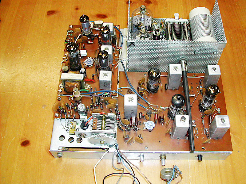
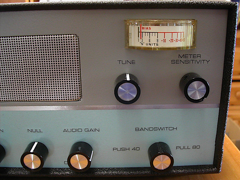
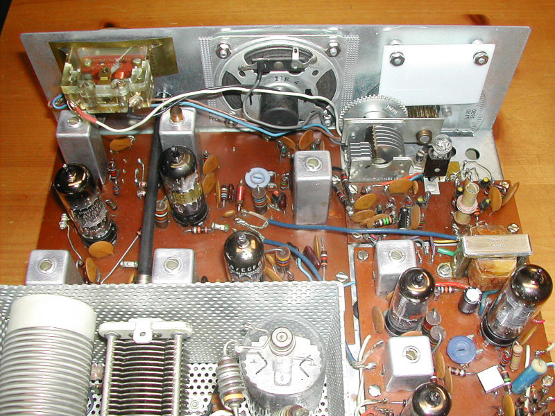
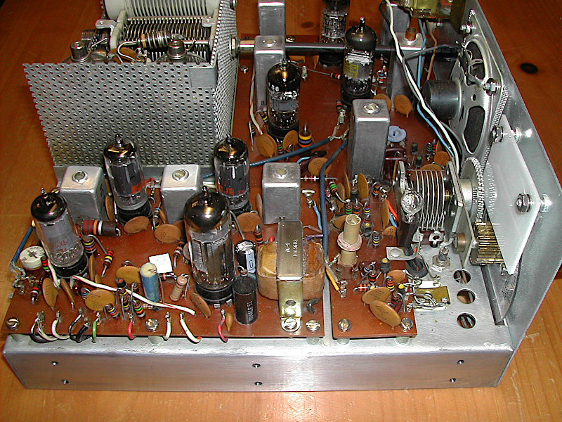
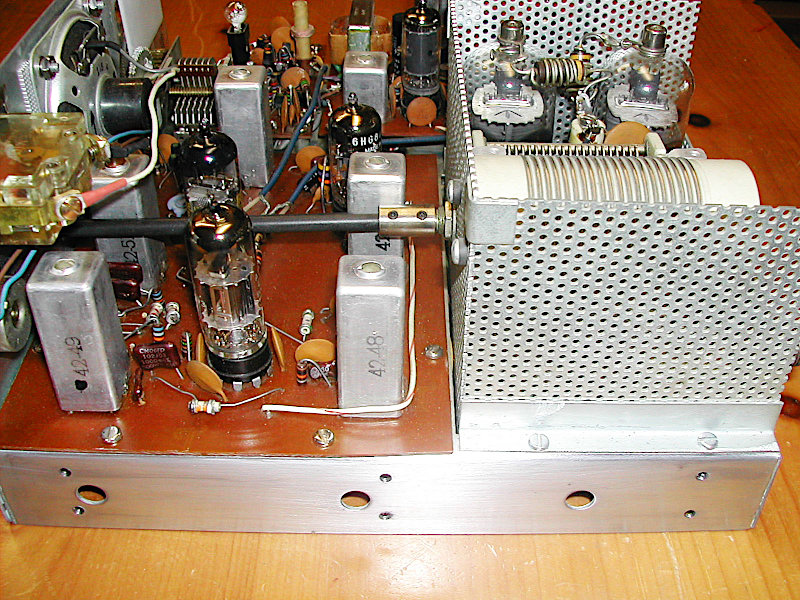
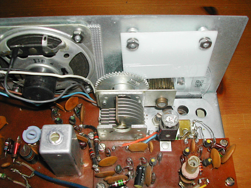
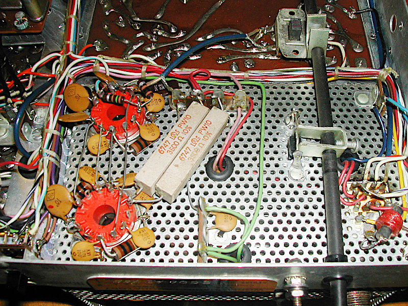
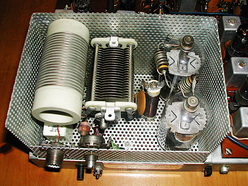
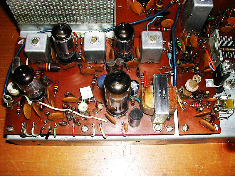
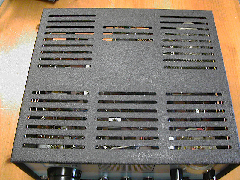
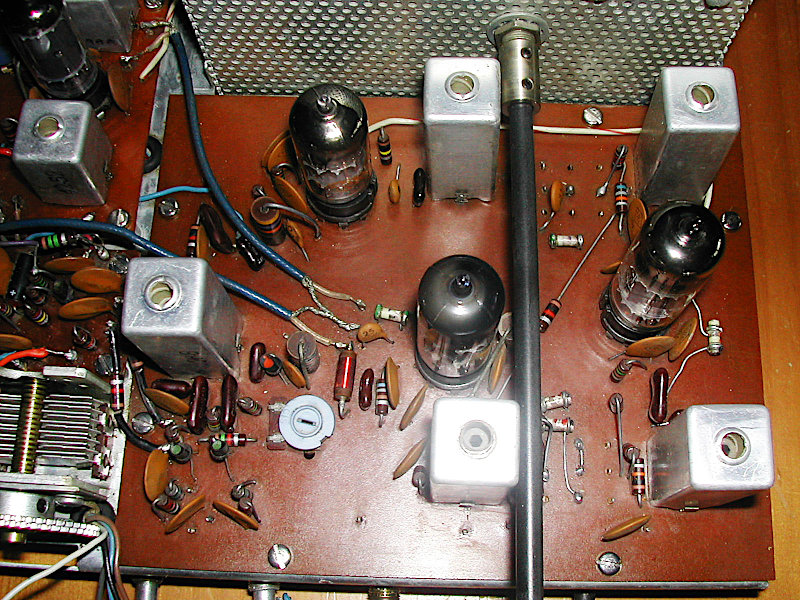
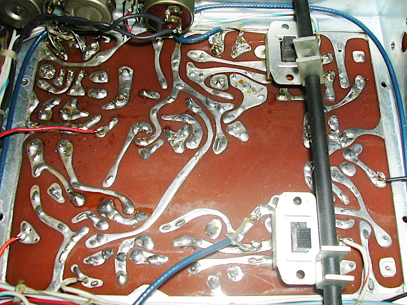
Electrically, the power supply had to be totally recapped. The transceiver had 2 resistors that had gone totally open. Replacing them and an electrolytic on the chassis bottom and 2 on the top restored the rig to operating condition. I did add a small pot into the S meter circuitry that now allows for both zeroing and sensitivity adjustments. The rear panel SO-239 was missing most of its phenolic. As a result the center socket fingers had opened and would no longer properly grab the mating PL-259 center pin. I had to make up some brass tubes on my lathe to slide over the center fingers and compress them. This also prevented the epoxy I used to refill the SO-239 socket from getting onto the center fingers. Replacing the SO-239 would have required extensive disassembly of the P.A. compartment. Hours were spent on cleaning the PC boards; they had accumulated years of dust and what appeared to be some oil. Lots of Q-tips and turpentine restored the boards back to their original shiny brown color. The vernier drive (which was removed when the front panel was removed) and its associated spring loaded split gears were cleaned and new lithium grease installed. The cabinets were straightened and sand blasted. The rig and power supply cabinets were then powder coated in a black wrinkle (textured) finish to match the original finish. All of the #6 hardware was also replaced as the screw heads had become very dull.
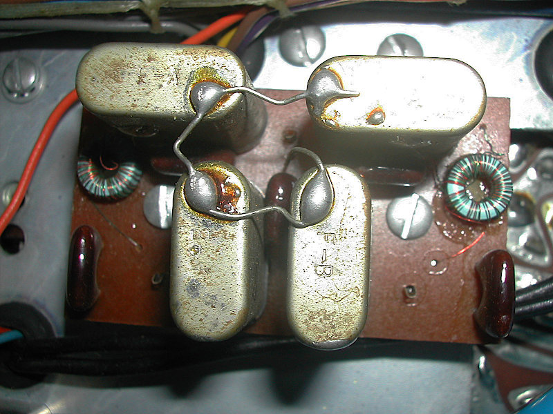
It was finally time to put the rig back in its cabinet. After that was done it was set up for photographing. But when I turned on the power, the P.S. groaned and smoke came out the lid. Some trouble shooting revealed that the low B+ line was shorted at one of the IF tubes. Initially I suspected a .01 disc bypass cap but the issue persisted after its replacement. Some more sleuthing showed the fault was a blue mini coaxial cable from an IF tube over to the TX board had a center conductor to shield short because the dielectric had melted away from too much heat. I had never worked on that coax so a previous owner or perhaps the factory had caused the issue. It never reared its ugly head all the time I worked on the rig and tested it on the air. It was replaced with Teflon RG-316 mini coax.
Given its production time of the mid 1960s, the rig has a surprising number of transistors in its compliment: 9 transistors and 9 tubes. The microphone amplifier, balanced modulator and VFO are all solid state. 2N2926 transistors (connected as Zener diodes) are used in the regulated voltage sections (balanced modulator and VFO).
Overall, this is a fun rig to use on the air. The VFO runs from 1.75 to 1.55 MHz. As a result of this low frequency, the VFO is quite stable. Band coverage is typical of the mid 1960s phone portions of 80 and 40M: 7100-7300 and 3800-4000KHz. The bands tune in opposite directions.
The bandswitch is unique. No rotary switch but rather three DPDT slide switches are employed. Thus changing bands is a push-pull operation as opposed to the normal rotary function.
Download the full Theory of Operation.
 |
 |
 |
 |
 |
 |
 |
 |
 |
 |
 |
 |
 |
 |
|
 |
 |
 |
 |