 All materials on this site © PAR Electronics, Inc.
PAR Electronics, Inc.
P.O Box 645
Glenville, NC 28736
Voice: 828-743-1338
Fax: 866-304-8479
Email us if you have questions or comments about this site.
Site by
Pinnacle Web Design
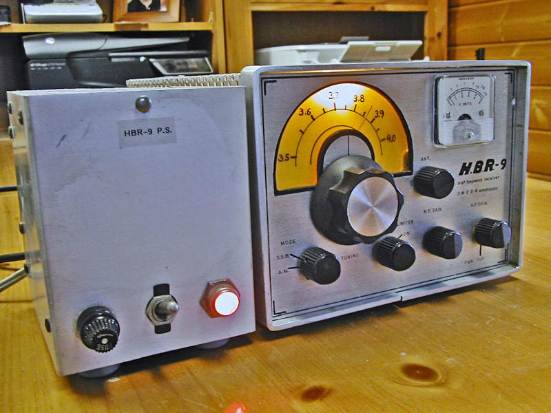
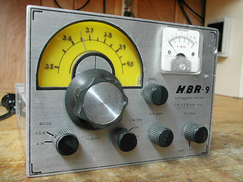
Vintage Radio Restoration - Omega Electronics 80M Receiver
I found this receiver in South Carolina after seeing a YouTube video of it.
It was missing a tube; without any docs, that is worrisome. My hope, which was realized, was that the empty socket was a spare — perhaps for future expansion — maybe a product detector.
Perhaps like most vintage gear, the receiver did not work when first fired up. All the tubes had been removed and DeOxit used on their pins. Controls had also been cleaned and DeOxit applied sparingly. Voltages were checked.
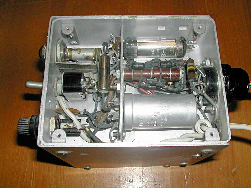
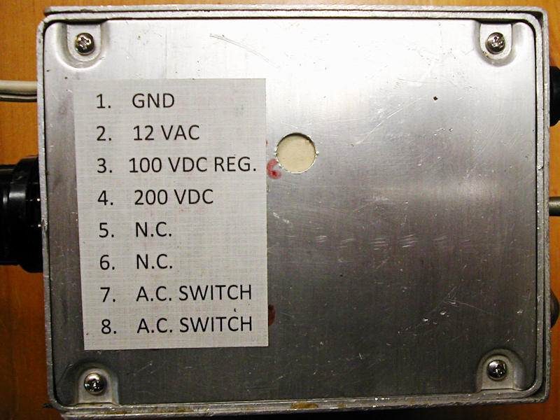
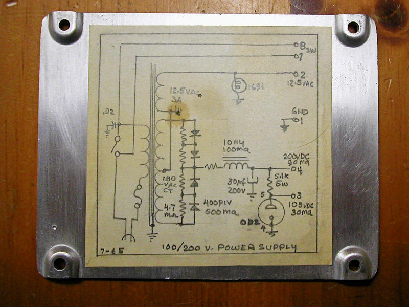
Fortunately, the power supply came with a schematic and pin out of the octal socket. I made up an appropriate cable and proceeded to finally get the receiver turned on.
As with all my BA gear, I run it on my bucking transformer — around 108VAC — and encourage others to do the same. The ANL switch was frozen and no amount of lubricant or working it loosened it up so that was replaced.
Firing the receiver up a second time brought noise but tapping the chassis resulted in loud static.
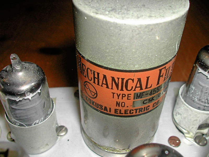
This receiver uses a Kokusai mechanical filter. I had 1st run into one of these on my KW Electronics KW-2000B. The delicate filter is held in place with plastic foam. Over time, the foam turns to goo and has to be replaced after cleaning up the mess. A jeweler's saw was used to make a cut around the base. After lots of cleaning and new foam, the filter was reinstalled and finally signals were heard, albeit weak. Tapping still brought loud crashes and signals would disappear. The designer of the receiver thoughtfully brought out a buffered VFO output to the rear panel. Out came the Rohde & Schwarz FS-300 spectrum analyzer. In this receiver the IF is 455KHz and the VFO runs 455kHz above the received signal frequency. I could see the VFO output as the chassis was tapped. A couple of hours later, I had located the problem to be a loose wire inside the Collins shielded VFO inductor. Now signals were at a good level and I proceeded to do an IF alignment. More appropriate, matching knobs were found for the ANT and main tuning.
The cabinet was joined to the receiver by sheet metal screws. These were all replaced by more reliable 8-32 machine screws after drilling and tapping the holes.
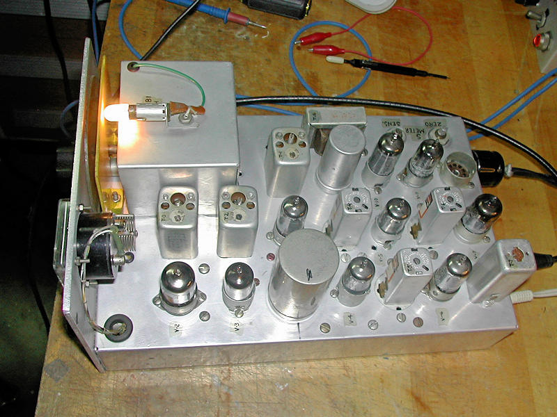
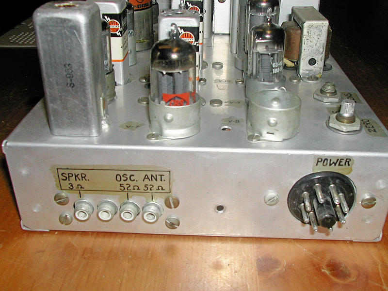
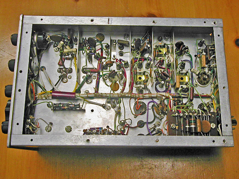
A lot of thought obviously went into this little receiver. The layout is very professional, wiring is well done and tidy.
Design appears to be straight-forward. VFO, Mixer, three 455KHz IF stages, AM detector, BFO and two stages of audio. The separate power supply generates filaments, 200VDC unregulated and 100VDC regulated. An octal plug/socket cable joins the two units.
As with most free-running VFOs, there is drift — always in the same direction — so it appears the use of some temperature compensating caps could reduce the drift. CW and SSB require the Audio Gain control to be run near wide open and volume adjusted by the RF Gain.
Attempts to learn who built the receiver have been unsuccessful. If anyone recognizes it, I would be grateful for any information.
Please click each image below to enjoy a larger view.
 |
 |
 |
 |
 |
 |
 |
 |
 |
 |
 |